Build the “Laser Messiah I” Laser Helmet for Hair Loss- Part III, “Wiring of the Laser Messiah”!
Step III of the WORLD RENOWN do-it-yourself instructions for the "Laser Messiah I" --"Wiring the Laser Messiah"! This is a full-coverage PROFESSIONAL STRENGTH laser helmet / LLLT Device --and I teach you how to build it yourself!!!
Step III of the WORLD RENOWN do-it-yourself instructions for the "Laser Messiah I" --"Wiring the Laser Messiah"! This is a full-coverage PROFESSIONAL STRENGTH laser helmet / LLLT Device --and I teach you how to build it yourself!!!
 Here it is! The last part of building your own laser helmet with OverMachoGrande...
You've built the helmet, you have the diodes, and you are ready to wire it! First of all...
Yep, that's the link to a printable PDF download. ...And this part, just like the other parts, require harldy any tools and/or skill!
This guide is a very conclusive wiring guide, so even if you aren't building a "Laser Messiah"... you can go through this and learn how to wire ANY sort of laser project! Just a reminder... I'm using AiXiZ diodes for this, and if your diodes are a little different, you might have to adjust my instructions to fit your needs! Ok, Let's jump right in...
SUPPLIES NEEDED:
From Home Depot:
• Wire Nuts:
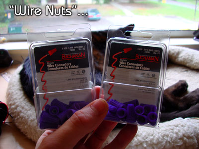
This is the first time-saver that RosarioRose9 at Regrowth pointed out for us! They make wiring connections ultra secure, and easy to add and remove diodes if necessary.
I can't remember the price, but these are no more than a buck or so for a pack of 25. I used 56, so yes... I spilled over into a third pack! There are a multitude of sizes, but I got the DARK BLUE ones and I felt that they worked fine. They are Buchanan "Wire Twist" Wire Connectors, 5 #20 - 3 #16 AWG, 73206.
• Wire-disconnects, both "male" and "female":
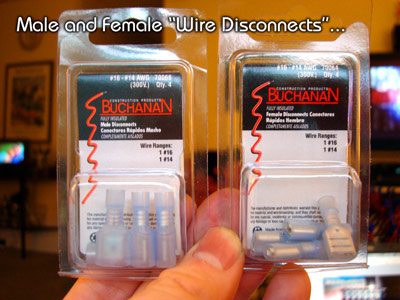
These are what we are going to use for the "switchable zones". Actual "switches" would require soldering, so "plugs" fit our needs much better! You need SIX PAIRS, so that means you need two boxes of male disconnects and two boxes of female disconnects (4 are in each box, and it's about 99 cents per box).
There are a few sizes of these, too, but I got the blue ones and I felt they worked fine. The are Buchanan Fully Insulated Disconnects, #16-#14 AWG, 70066 (male) and 70064 (female).
• "Sturdy Twists" twisty ties:
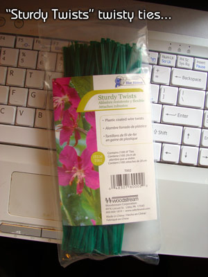
Ok, I really didn't need to put these up here because most people have twisty ties laying around there house from bread, electrical cords, etc., but I've searched for these in stores FOREVER and I've never found them until now. I was elated to find these in the GARDENING SECTION (hence the green color) at Home Depot! I much prefer twisty ties to cable ties because you can undo and redo twisty ties, and you don't have to use pliers to remove them like you do with cable ties!
Anyway, if you've been searching for them, too... they're in the gardening section for only a couple of bucks tops (if even that much) for a pack that will last you for a really long time! They are a really easy way to organize ALL of your wires in your house!
From Radio Shack:
• Red and Black Wire:
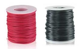
Pretty much any wire is fine, but Radio Shack has these that work well:
90-Ft. UL-Recognized RED Hookup Wire (22AWG) - $4.99
100-Ft. UL-Recognized BLACK Hookup Wire (22AWG) - $4.99
You'll notice that the black wire is SOLID while the red wire is more like typical wire (made up of a bunch of smaller wires), but they both function great!
• Automatic Wire Strippers:
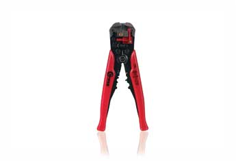
This is the second time-saver that Rosariorose9 from Regrowth brought to us! They are $16.99 from Radio Shack (and you can find them in a lot of other places, too), so they aren't exactly cheap but the time this one tool saves make it INVALUABLE. I wouldn't make a laser helmet without them. Literally, it turns one of the hardest tasks into one of the easiest tasks, and literally will save you hours and hours!
This one from Radio Shack (as most other "good ones" probably) will also serve as a wire cutter and a crimper for the wire disconnects. All and all, it's a very important tool that everyone should have, and like I said... we can use this for three purposes on this helmet!
The laser diode wires are very thin. I'm not sure what gauge they are, but they are probably around 24 gauge, so make sure that your automatic wire stripper will go up to that gauge!
• Barrier Strip (six position, dual row):
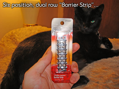
This is the backbone of the "Flux Capacitor" that we will make, which is just my joking term for describing the device that takes the power from the power supply, splits it, and has "plugs" that allow us to make the "switchable zones".
They sell these at Home Depot, too, but I used the Radio Shack one. Couple of bucks maybe? Maybe as much as three? Radio Shack is starting to get really expensive for their little tiny things that cost a half cent to make! lol...
Other Supplies:
• Super Glue Gel (you probably have this left over from the first step)
• Velcro (you probably have this left over from the first step)
• Philips head screwdriver
• Small flat-head screwdriver
• Wire cutters/diagonal pliers (I actually used them instead of the automatic wire strippers for the WIRE CUTTING part, but you don't have to use these. The automatic wire stripper will work fine.)
Did you notice something?? No really hard-to-use tools, and no SOLDERING! This helmet truly is... the "Laser Messiah"!
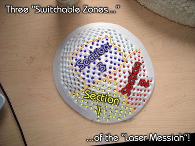
PROLOGUE: Switchable Zones and Soreness... an Added Benefit to Laser Therapy for Hair Loss (???)...
As you already know... I'm writing these instructions to include "switchable zones":
I'm going to explain WHY now! And it starts with some history...
When I made my first laser helmet, I didn't know if any of this would work... meaning, I didn't even know if the diodes would LIGHT UP! Yeah, and of course I wasn't *sure* that it would give regrow hair, either! lol... Well, of course the answers turned out to be a resounding YES for both of those, but pre-December 7th, 2007 (the day I first threw on the switch of my first laser helmet) I was reluctant to sink a lot of money into something I wasn't sure about.
So, after I made my first tin foil template:
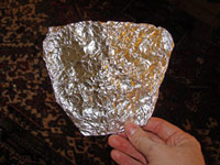
...I stared at it and realized that I could make a "cluster" that I could move three times to cover everywhere:
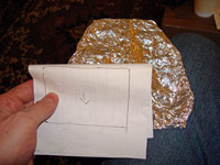
...thus saving me MONEY! I only need 1/3 the diodes (which were still $4.00 apiece at that point... thanks again Nidhogge for getting us a deal).
So, I got the gutter guard and marked the area that fit my "cluster" size that I drew on that piece of paper:
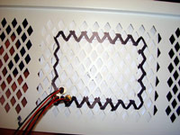
...And I came up with a number of 68 diodes, with rows in a pattern of 8 x 7 x 8 x 7 x 8 x 7 x 8 x 7 x 8. Also, to accommodate the "bowing" that occurs from sticking so many diodes in a piece of plastic like that...
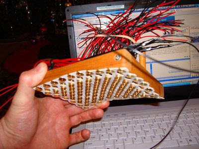
...I thumb-tacked the diodes to a wooden frame that had an arch in it to somewhat replicate the curvature of my head. So that is the story of how I originally determined the number of diodes I used for my first laser helmet... and the main reason was MONEY! I just didn't want to potentially waste a whole lot of money that -at that time- I wasn't even sure would even function!
Ok, so I started to use it. I found VERY QUICKLY that, WOW... my scalp muscles were getting SORE. ...And it wasn't the skin or the tissue getting too much stimulation (I was using it 20 minutes in a section, which worked out to be somewhere around the 4 or 5 joule mark if not a little more, so it was a good amount of time), it was the SCALP MUSCLES. Yes, the muscles that are even BELOW the depth of the follicles.
Well, as you know, I was 1) the only one doing this for a while, and 2) people that go to laser clinics DON'T POST IN FORUMS (why should they... they regrow their hair!), so I though that was the way it was SUPPOSED TO BE! I *assumed* that laser therapy must also exercise the scalp muscles, and no one told me any differently! I thought that everyone would be experiencing this same thing.
Well, after a few months, others started to make their designs and use LLLT, too, and they took my advice about what I felt were flaws of my design (my flaws were that I felt I wasn't getting even enough coverage because the cluster was at varying height above my scalp -which could be solved by resting it on brush bristles- and I felt that I was potentially overlapping my cluster sections too much and therefore giving too much energy to some areas-which could be alleviated by having a device that gave "FULL COVERAGE" to everywhere at the same time). So, they were using full coverage devices with lots of diodes... but WEREN'T GETTING SORE. At least not like I was. Then, the lasermax users started reporting that they weren't getting sore, either.
This was extremely baffling to me! I assumed that if I was getting sore by moving a cluster three times, they would get MORE SORE by exposing a larger area at once. What the hell? Was it just that I had week scalp muscles or something?? This was confusing! Plus, it's not like my soreness was happening only on the overlapping zones... it was the entire scalp muscles!
This is where it gets really interesting... Jdp710, who also had a cluster of 68 (technically 67 because one of his burnt out, but I'm still going to call it a "cluster of 68") started reporting the EXACT SAME THING I DID. He would get very sore also!
And to reiterate... this soreness is NOT from overexposure with the lasers. Take this into consideration... people can use their "full coverage" devices for 45 minutes, and still don't get much, if any, soreness. When they do that, they are getting probably way too many joules over their entire treatment area, too! Yet, no soreness! However, when jpd710 and I do something like change the time period of each of our three zones to 30 minutes instead of 20 minutes... it becomes almost UNBEARABLE to do it because of the soreness of the muscles! It's like you are trying to bench press "triple wheels" with your scalp muscles or something! Literally, I *couldn't* do it for 30 minutes in each section -I've had to stop short every time I've tried it- even though the people with full coverage devices -laser helmet or lasermax (and probably clinical laser devices, too)- could easily do it.
Now, lets add this data to the equation: people that have clusters with a lot less than 68 (anywhere from 20-40 diodes or so), DON'T REPORT SORENESS EITHER. So, it seems that the cluster has to be a big enough size to do this, and the 68 is big enough, and 20-40 is too small.
HERE IS THE CRUX... Jdp710 and I (as well as a few others out there that don't post in forums but I speak with through email) have reported QUICKER, MORE PROFOUND RESULTS THAN OTHERS DOING THIS. I'm obviously not saying that the others *aren't* getting results -they clearly do, and the laser clinics OBVIOUSLY do- but I'm just saying that the people that are reporting this soreness 1) have clusters that are pretty big, 2) they move it at least three times, and 3) are getting QUICKER results!
Yes, this absolutely could all be coincidence. I am completely aware of that! ...But I don't think so. There is too much other corroborating data that we can take from the other devices that back this up. That's why I've formulated this hypothesis:
If you have a BIG ENOUGH cluster of diodes and move it several times, it makes enough energy to stimulate enough area of the scalp muscles that -EVEN THOUGH YOU ARE STILL ONLY GETTING THE PROPER 3-6 JOULES AND NOT GETTING TOO MUCH ENERGY- the device has an EXTRA BENEFIT OF BEING A "SCALP EXERCISER"! The scalp is still getting a FULL HOUR (or whatever the TOTAL treatment time is) of working out. AND... the added benefits of this extra stimulation could very well equate to much more production of N.O., S.O.D., etc. and all the other things than you otherwise wouldn't get as much of, and these are things that people far smarter than me have decided must be present for a good hair re-growth environment!
Yes, that's right... it's a "scalp exerciser". I'm sure that most of us are familiar with the scalp exercise guru and forum at http://hairloss-reversible.com. If not, to sum it up... there is a guy that maintains that scalp exercises will prevent baldness and regrow hair. Now, he *could* be right for all I know, but I -and most other people that have tried them- don't know because doing scalp exercises are a royal pain in the ass. To have to do something like that for 20-30 minutes every night or three times a week for a long enough period of time to show benefits is NOT in my interest! Now... the few people that HAVE DONE these for at least six months *do* report some results, that can't be denied... it's just sticking with them for most people is a burden, not fun, and just not "do-able". Therefore, the sample pool of people that do scalp exercises for a long enough period of time is really to slim to make any solid deductions.
However, with this "moveable cluster" thing that we have stumbled across, not only are we potentially doing "scalp exercises", we are "working out" the scalp muscles far better than those scalp exercises could EVER DO. I've tried those scalp exercises on that website for about two weeks (and I stopped them from boredom), and I can personally attest that there is no way you can get your scalp muscles as sore as this by them.
Once again... in case you've already forgotten, the people that report the soreness are the ones with the large, moveable clusters (68 diodes), and we are the ones that are reporting the quickest results. Yes, none of this is PROVEN... in fact, this could *all* be the result of overlapping areas! I don't think so, though, and if you've paid attention to the evidence I've shared, you probably don't either! It's all based on our actual observations using it, but it's definitely a solid hypothesis.
Therefore, in summary, I felt it was CRUCIAL to make a device that would have "switchable zones" so I could continue to check this. Plus, with a device that has diodes over the entire scalp, you are eliminating the risk of overexposure due to the fact that there aren't any "overlapping areas" anymore! PLUS, if for some reason we find that this isn't worth it or just want to save time and treat the areas all at once, we have that option!
The choice is YOURS with this design... you can use the "switchable zones" or you can use it as a "full coverage" device! I feel this device has the most options, and potentially could benefit you in a "brand new way" that other laser devices don't. That's only my opinion, but like I said... it's one based on evidence that people have reported.
So, you certainly don't have to build it this way, but I hope you do. I'm looking very forward to hearing what other people report about this in the future!
-O.M.G.

SECTION 1: Choosing the Proper Power Supply...
Determining your requirements is easy enough. Our AiXiZ diodes are 3.2 volts, and 30 milliamps. If you are using another type of diode, then ask the manufacturer what the specs are. Ok, I'll go into both volts and amps a little deeper...
VOLTS: First of all, let me say that even though the diodes are "3.2 volts", you aren't going to find a power supply that is "3.2 volts"! You will find them at 3 volts and 3.3 volts, and both of those are fine! In fact, I'm going to refer to anything with a three-point-whatever as "3 volts", and completely forget about any decimals from here on out, ok? lol... Our diodes have some circuitry built in that takes care of all of this magic for us, so we shouldn't worry about it. I, however, wouldn't risk going up to five volts... that might be pushing it.
Ok, with the way we wire the diodes, the volts stay the same throughout the helmet. That means that since the diodes are three volts, we need a three volt adapter. Easy enough, right?
AMPS: Our diodes are 30 milliamps, so that is obviously .030 amps. Unlike volts, you actually add up the amps of each diode. So, if you have 10 diodes, that would be 10 X .030 = .3 amps. If you had 100 diodes, it would be 100 x .030 = 3 amps. And so on... Well, I have 217, so that's a total of 6.51 amps required at a minimum!
So, in my case, I need to find a 3 volt power supply/adapter that has at least 6.51 amps.
Well that's easier said than done. It becomes fairly hard to find power supplies that meet that spec. However, you *can* find them (just not at Wal-Mart or Home Depot), and I try to keep a current list on my website on the "Power Supplies / Adapters" page, which is linked to in my "Supplies" section on the sidebar. There are a few options there, including the ability to make or buy converted computer power supplies (Hapyman at Regrowth can make them).
I'm not covering any special modifications of power supplies in this document. All you need to do to make ANY proper power supply work with this helmet is install the proper "wire disconnects" (don't worry, I explain what those are when the time comes) so it can connect to and disconnect from the back of the helmet. ...And by the time you are finished with the wiring, you'll be such a pro that none of that will need ANY additional explanation!
That is truly all you need to know about choosing the proper power supply for laser helmets!
SECTION 2: An Overview of Wiring, and establishing the terminology
For more details on the basics of wiring -including some graphics- go to http://www.overmachogrande.com and look at my page "Wiring is ridiculously easy!" located in the "Must Reads" section on my sidebar. All you need to know is this simple fact: ALL OF THE RED DIODE WIRES end up connecting to the positive side of the power supply, and ALL OF THE BLACK DIODE WIRES end up connecting to the negative side of the power supply. Nothing red ever connects with anything black! Got it? Good!
Ok, now obviously, you have to have some steps or phases in this, because -as in my case- 217 diode wires are impossible to bunch together and connect to one power supply wire! Right?
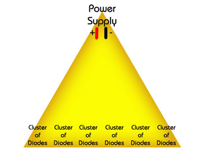
So... we need to set this up like a "pyramid", with the diodes being the bottom level, and the power supply being the top...
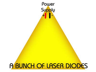
The diodes are first clustered into groups of 8-10 diodes, or whatever number suits your design the best (the number isn't important).
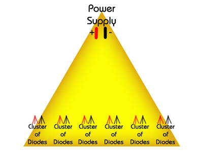
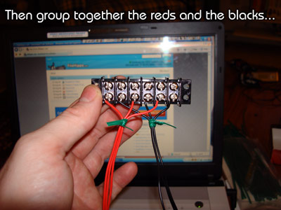
Then the diode wires are separated and grouped so that all of the reds are together, and all of the blacks are together:
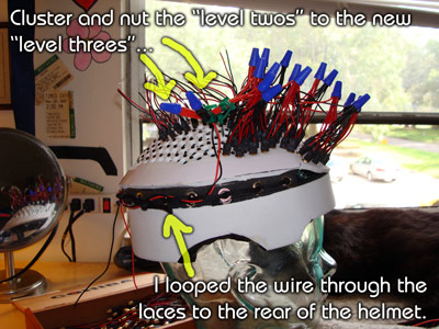
So, we need to now connect all of the reds together and all of the blacks together with connection wires. Ok, now for some terminology. In order to establish some terminology that makes it more understandable for everyone, I'm referring to these connection wires as "LEVEL TWO CONNECTION WIRES".
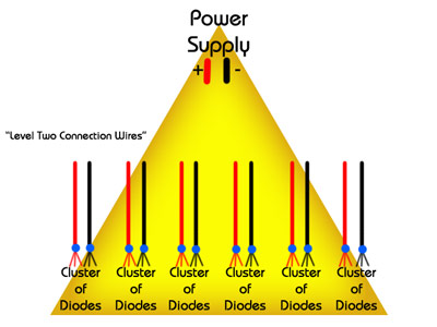
So, we connect the "Level Two Connection Wires" together...
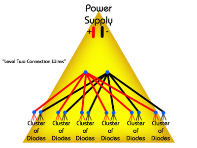
And then, we add another term here, we add the "Level THREE Connection Wires", which in the purpose of this illustration is the last step and consists of two wires that go directly to the power supply...
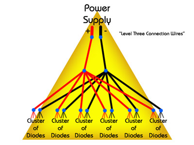
Now, in REAL LIFE, because we are having three "switchable zones", we are going to have three "Level Three Connection Wires" that connect to our next bit of terminology that we are going to use, the "Flux Capacitor"!
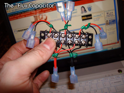
As you know, we aren't actually going to have "switches"... we're going to have PLUGS to control our "switchable zones". This "Flux Capacitor" splits the incoming power three ways (one for each of the three sections) and each section has plugs that you plug in or unplug to control whether it's on or not!
SECTION 3: Preparing the diodes...
I'm going to say this again, if you get an "Automatic Wire Stripper" like my Kronus Heavy-Duty Automatic Wire Stripper/Cutter from Radio Shack ($16.99), you will not only save HOURS, you will have much more success and much fewer errors -if not ZERO! PLEASE, go get one. Whatever type you get, you want to make sure that it will strip 24 gauge wire. I'm not sure what the exact gauge of the diode wire is, but it's very thin, and this wire stripper will indeed strip it!
At the time I'm writing this, I want to point out an error on the Radio Shack web site. The cheaper $9.99 wire stripper says that it will strip up to 24 gauge on their online description, but when you see it in person... it clearly states that it will only strip up to 18 gauge wires. I literally just sent them an email regarding it so maybe they will change it... but you and I both know how big companies work. Is that email even ever going to be seen by a living person?? lol..
Back on topic, credit where credit is due! Once again, I thank Rosariorose9 at Regrowth for opening up the wide world of automatic wire strippers for us (the SECOND huge time-saving contribution he's made to wiring)! He literally saved me hours and hours of time on the stripping. It used to probably take me over a minute, maybe even two, to properly strip both diode wires -and that time adds up when you have 217 diodes- and now I can strip both wires at the same time in about 5 seconds! lol...
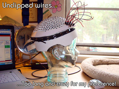
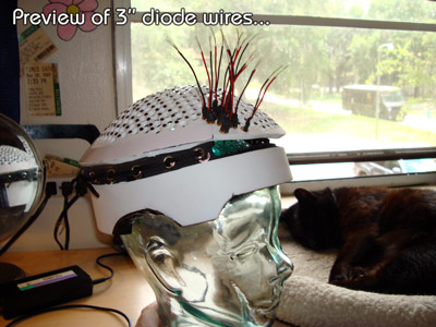
Ok, let's look at something. These diode wires are roughly about 6" when we get them.
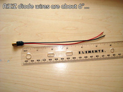
If you were to put them in the Laser Messiah at that length, it's just a little but too crazy for my taste!
So, we need to cut them down, and as you can see in this "preview", the diode wires look and behave a little better trimmed up:
And here is another "preview" that shows what you've got when you add the wire nuts (without the "level two" connection wires)...
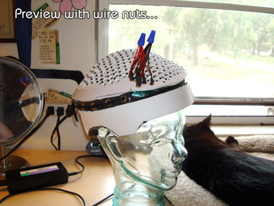
So yes, still crazy, but not quite AS CRAZY, and it meets my standard of looks!
1) Trim the diode wire...
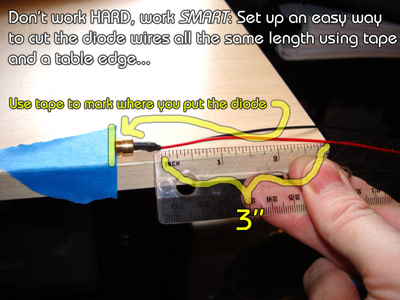
Ok, so let's cut them! Now, keep in mind that we still need SOME length on them to work with, so don't cut them too short. I decided that 3" would be a length that still gave me enough length to work with as well as look much better and be easier to control.
i]WORK SMART! I used some tape to mark where I place the tip of the diode on the edge of the table that would give me 3" of diode wire:
Now you cut it with wire cutters/diagonal pliers/whatever you want to call them...
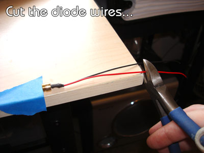
And you're left with a diode that has 3" of wire vs. 6" of wire, and that's much more manageable, isn't it! So go ahead now and cut all your diode wires! Yep... depending on the number of diodes you have, you may be doing that a while! That's why we set up an easier way to do it with the whole "tape on the table" thing!
2) Strip the diode wire...
This is where the magic of the automatic wire strippers that Rosariorose9 told us about comes in!
If you are just scanning through this, don't worry if this picture looks confusing because it makes sense when you are actually holding it in your hands...
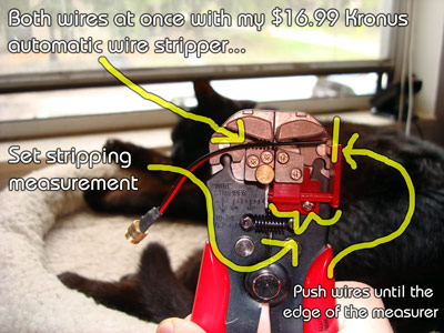
You need somewhere between about 1/2" and 3/4" of exposed wire for the wire nuts, so set the red stripping measurement thing to about that width (I just pushed it all the way in and it worked fine!). Notice that I can cut BOTH wires at the same time, too! That's just amazing!
...and when you squeeze the stripper:
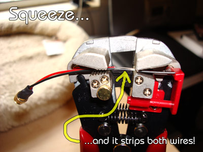
You see the magic happening! lol...
So, you are left with perfectly stripped wires somewhere in the 1/2" to 3/4" range...
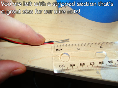
...which are a great size for the wire nuts! Now, go ahead and do this for ALL your diodes, and then we are ready to start putting them in your Laser Messiah!
Soon, you will be left with a nice cigar box full of much more manageable looking diodes with enough bare wire for wire nuts!
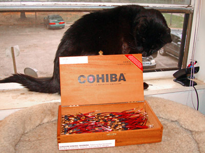
Wait... you *do* smoke cigars, right??
SECTION 4: Testing the diodes...
This part is completely optional. The fact is, the diodes SHOULD work, but we know that we don't live in a perfect world. If you already have a power supply, you might want to rig it up so you can very easily check and see if the diodes are working.
All you have to do to test a diode is to BARELY TOUCH the red wires of the diode to the positive wire of the adapter, and the black wires of the diode to the negative wire of the adapter.
At the time I'm writing this, I don't have my power supply yet, so I have to use an older one for the pictures. Sorry about that! But you guys have already gotten so far that you probably already know how to rig up a test with your own power supply so I don't feel so bad! lol...
Here is how I rigged it up:
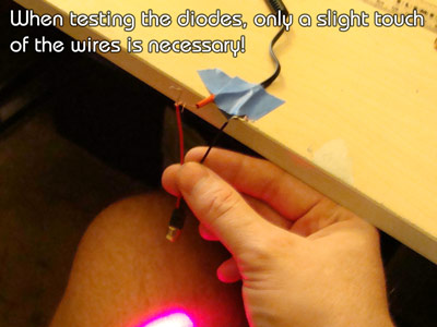
I just taped the wires from the power supply in a fixed position and all I do is barely touch the appropriate wires together. If it lights up... congrats! That diode works! Literally, I could test one diode probably every five seconds or less so this didn't take long at all!
On a side note... I can't believe I actually took the time to test these, though! lol... Do I have a fever?? Am I "growing up"?? That's not normally my behavior at all! Well, now I know that if they don't work on my helmet, then it's probably something [ i]I DID!
SECTION 5: Putting the diodes on the helmet...
Before we start this, I need to make two quick notes. First, a quick note about orientating the diodes...
You can attempt to orient the diodes in the helmet to have a more uniform coverage, but I'm going to warn you that when you get that helmet on your head, the curvature of the scalp is going to make it so that it's nearly an impossible task! So, I'm not worrying about it that much. Remember, it's all about averages and long term usage, and no matter how or where the laser footprints land, they are going to move around a little due to shifting of the helmet.
Ok, but I *am* going to do this. It's probably not 100% of the time, but I've notice a definite tendency towards a trend here...
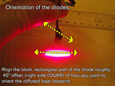
When the flat black part of the diode is DIAGONALLY ORIENTED (from top view) so that the top is on the left and the bottom is on the right, then the rectangle will be straight left-to-right!
Like I said, this may not be the case 100% of the time, but it's enough that I noticed it with my first laser helmet, and I tried it on about 6-8 diodes and it was indeed the case!
So, I will attempt to put the diodes in the helmet at this uniform position!
The second quick note is about gluing in the diodes...
The diodes all-in-all fit pretty snuggly in my holes because I properly tested them out before I put the holes in the top of the helmet. However, you might find that when you start putting the diodes in the holes, once you start getting a lot in the area you will accidentally start PUSHING OUT diodes when you are trying to exert enough force to PUSH IN the other diodes! So, with some holes, it may be necessary to use a little bit of super glue.
Yes, this DOES mean that these diodes will be harder to get out if one fails, if you want to spin it to try to orient it better, etc. However, we tested them, right? They should work! lol...
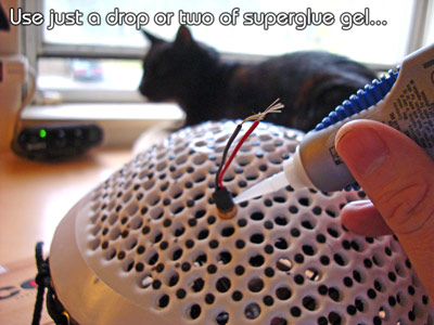
Ok, a DROP or two at the most of super glue will suffice. BUT PLEASE, remember... we want to keep that glue away from the tip of the diode! If you got some superglue on the tip of the diode, you're probably screwed, Homie!
So, do this. First, insert the diode at least halfway into the hole:
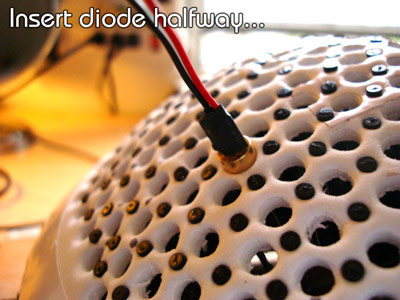
Then, put a DROP of superglue gel...
...and push it all the way in, flush with the surface!
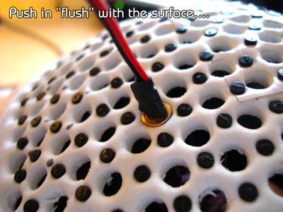
That should be plenty to withstand some force! I must say that yes... I *did* use a drop of superglue gel on every diode. Do you have you? *Should* you?? That's up to YOU... you're the executive decision-maker of your helmet, and you know better than anyone else on god's green earth! Ok, now that we've covered those two points, we are set to move on!
You know... let me add one more absolute rule to this section's preface: DIODES TRUMP BRISTLES! Make sure the DIODES are in the proper position. The bristles may point in funky directions while you are doing this, but don't pay them any attention. After you've finished, you can attempt to straighten them out, but more than likely... they'll work themselves out!
Ok, NOW we are set to move on!
1) Establish your borders!
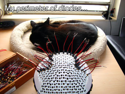
Since we want to make sure that we put them in the right place, start with the perimeter!
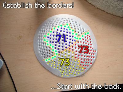
Here is what my perimeter looks like:
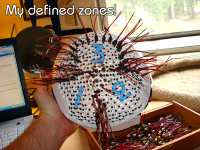
2) Establish your ZONES!
If you are choosing not to make "switchable zones", you can skip this step, but for those of us trailblazers and experimenters that are... put in diodes to mark your zones!
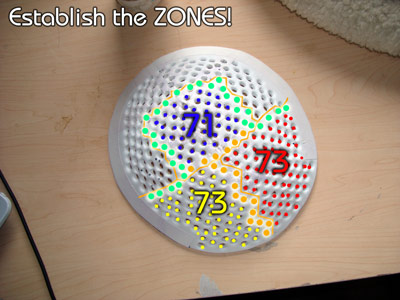
Just make sure you remember which cluster the diodes belong to! In my case, I chose to mark the zones with the diodes of the REAR section, and the diodes of the LEFT section.
Here is mine so far:
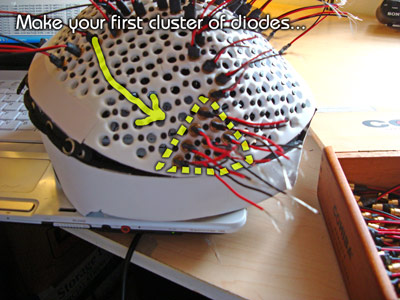
3) Complete the first zone! "Cluster and Nut" as you go...
If you think it looks like you have a lot of free, crazy wires now, you should see what it looks like with ALL the diodes in place! Fortunately, you're not going to see that because we are going to "cluster and nut" the wires as we go! This means that we are going to use wire nuts and connection wire in this step.
The wire nuts I have easily hold between 8-10 diode wires with one "level two" connector wire. So, we will try to put in between 8-10 diodes at a time, separate the red and black wires, twist all of the reds with the red "level two" wires and put on the wire nut, then do the same with the black! ...And we repeat this until the entire cluster is filled.
Just a note, it doesn't really matter how much is in each cluster. It doesn't make any practical difference in the distribution of power. If you have to make one or two with 2,4,6, whatever... it's fine!
Also, I firmly believe it's better to have too much than not enough, so when it comes to the "level two" wires, I make them VERY LONG. That way we will have the most options we can possible have when it comes to arranging the diode wires neatly!
Ok, let's illustrate everything that we just covered! First, place 8-10 diodes in whatever first area you choose (glued or not depending on your wants and needs [and remember I did glue mine and I'm very happy that I did]):
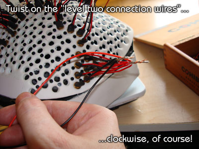
Then, you are going to group the black and red wires separately and twist them together. Before you twist them, you want to make sure they are as aligned as possible:
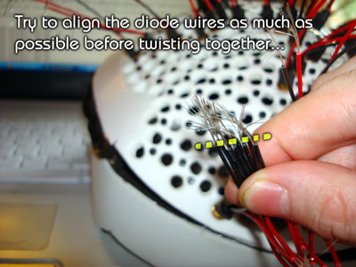
This will make less chance that there are exposed wire areas below the wire nut when we screw them on. Here is what it looks like after you twist the wires together...
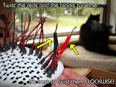
...and it's best to twist everything CLOCKWISE! Yes, the righty-tighty rule is in effect here. You want to twist everything the same way so you don't cause problems by accidentally twisting the wire nuts the opposite way of the diodes. Make sense?? Good!
Now you are also probably understanding why we didn't cut the diode wires shorter! If you pull a diode wire to hard, it will make that diode point in a direction other than straight down! That means that you should really focus on keeping the clusters as "tight" and un-spread-out as possible.
Ok, now we need to cut the "level two connection wires". Remember, we can't just wire all of these diode wires together because there isn't a wire nut in the world big enough! Therefore, we have to make "levels" of wires that eventually taper down to only two wires that connect directly to the power source.
Make sure that the wires are long, too....
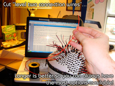
In fact, I made mine at least twice as long as they had to be -as I always do. I'll point out that I've made two complete laser helmets and a laser brush, and I still have some wire left! ...So you don't have to really worry about using the wire sparingly!
Ok, strip the end of those wires, twist on the wires, and yes... twist them the same way (clockwise) as you did the others:
Finally it's time to twist on the wire nuts....
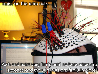
Yes, grasp all the wires with one hand and twist on the wire nuts with the other hand pretty darn hard! You'll know when you do it right... you'll get it so you can't twist it anymore! Oh, yes, you CAN twist it too much and have the wires break, but it's pretty hard to do. Just stop when you can't twist it anymore.
The idea here is to cover all of the bare wire. If you have bare wire exposed because the diode wires were too uneven, you can always use some electrical tape to cover it.
So, the idea is to "Cluster and Nut" as you move along...
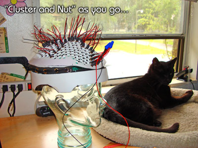
And finally, you are finished with the "clustering and nutting" of the first section:
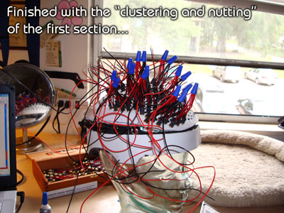
...even though it looks really messy right now! Well, let's fix that!
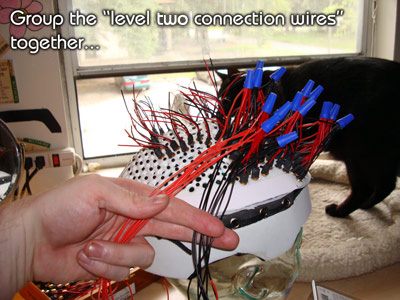
Group the "level two connection wires together"...
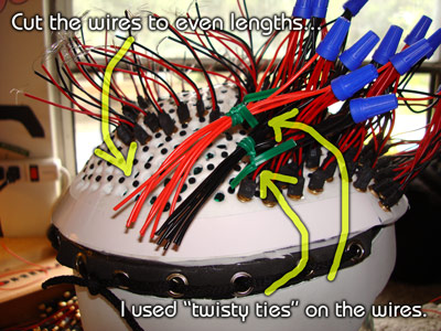
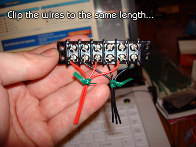
Now, cut the wires to equal lengths, and use 'twisty ties" if you need them...
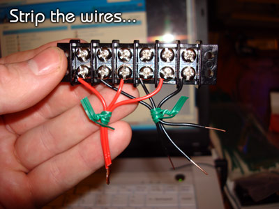
Strip the ends of the wires...
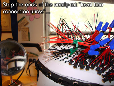
...CUT LONG "LEVEL THREE CONNECTION WIRES", one for each color (no picture for that!), and wire nut them together, too!
NOTE: These wires are a lot thicker, so I probably would have been better off using a larger size of wire nut. However, I didn't. I just smashed them in and twisted them together as best as I could. I ended up having bare wire exposed, so I covered that bare wire with electrical tape, and PROBLEM SOLVED! I used electrical tape on six of these "level two to level three" connections, by the way.
Ok, so now... all of your diodes in Section one are reduced down to one "Level Three Connection Wire" of each color! Now, if you've rigged up a way with your power supply to test your diodes, you might as well test them here, too:
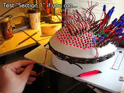
...And you are finished with section one!
4) Complete the second zone!
Start clustering and nutting in your next section...
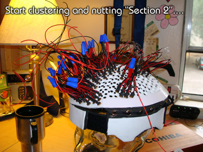
...and bring the "level two" wires off of the other side of the helmet.
After you are finished with that section, test it if you can...
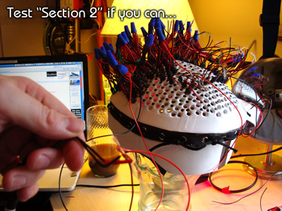
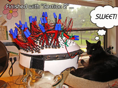
...wrap the wires through the laces and bring them around to the rear, and here is "Section 2" finished!
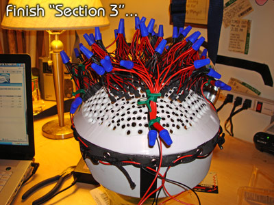
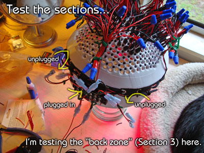
5) Complete the third and final zone!
Repeat all of those steps and finish section three:
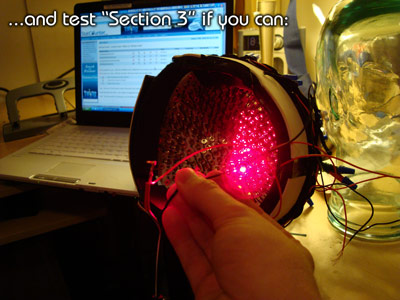
...And test "Section 3" if you can:
Just a reminder, I was short a few diodes (four to be exact):
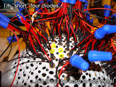
...but that's no problem. As you just learned, it's so easy to wire and rewire these things, all I have to do is put the diodes in, add them to a cluster with a "level two connection wire", and I'm set! No big deal, and I could do it in less than 10 minutes I'm sure! My missing diodes are already ordered and on the way...
Ok, here is the bottom view...
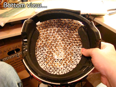
...and yes, at this point you are allowed to try to move the bristles a bit as well as make sure the diodes are oriented properly! But hey, you are FINISHED WITH THE DIODES, and it's smooth sailing from here on out! lol...
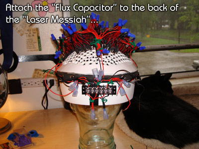
SECTION 6: Building the "Flux Capacitor"...
Ok, as you know, the "flux capacitor" is the name we are giving our "switching device", which -of course- really isn't a "switching" device, it's a "plugging" device! So, this is what we do.
Get the six position, dual row "Barrier Strip"...
The idea of the "flux capacitor" is to bring the power in from the power supply, split it into three sections, and have plugs on it that each of our three diode zones can plug into.
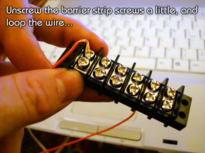
So, the best way to do this is to wire the barrier strip red-black-red-black-red-black. We start by unscrewing the screws of the barrier strip, and cutting some wire (I actually used spare pieces laying around from the cut "level two connection wires", so they don't have to be really long). Then we loop the wire:
Obviously, screw on the wire...
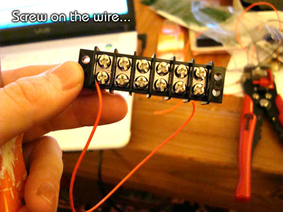
...and alternate red-black, red-black, red-black:
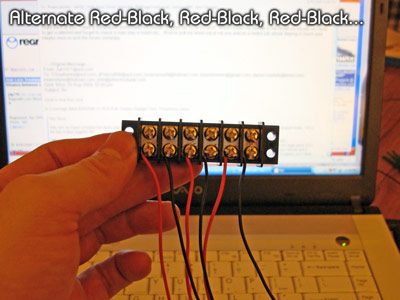
Then group together the red wires and the black wires:
...and trim them up nice and tidy:
...and, of course, strip them:
Now is the time for the male and female wire disconnects:
I covered this in the supplies sections, but I'm going to cover it again! It is MANDATORY that you stick a flathead screwdriver into the female disconnects to widen them up:
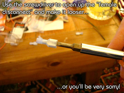
This makes it so the connection isn't quite so permanent, and we can actually use them as "plugs" that can easily be "un-plugged"! If you make them too wide, you can always use a wrench (I used my TEETH) to crush them a little again to tighten them back up!
Ok, now that we covered that, let's continue!
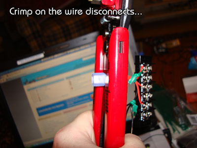
Crimp on the wire disconnects:
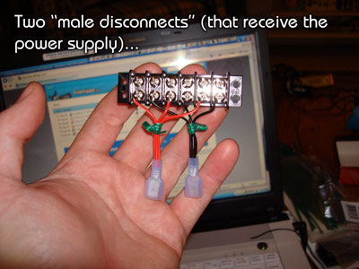
You can use whichever ones you want (male or female) as long as they match up to their opposite partner! Just for simplicity, I made all of the "Flux Capacitor" disconnects MALE. [However, now that I've made it and used it, I would have preferred to have used all FEMALE on the Flux Capacitor" and the males on the helmet "level three" wires because of the way you plug and unplug them. You may want to do that.]
So, do the same with the other side, and you have this:
So yes, this is where you plug the power supply in! That means that the power supply chord will have two female connectors on it. I'm not covering that step in these instructions, though, because at the time I'm writing this I don't have the power supply I'm going to use!
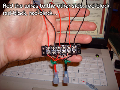
Now we are going to add wires to the other side, just like we did to the bottom (red to red, black to black):
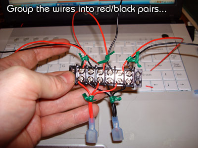
Now group them into pairs with twisty ties...
Now you are going to move them to the left, center, and right, and trim and strip the wires evenly:
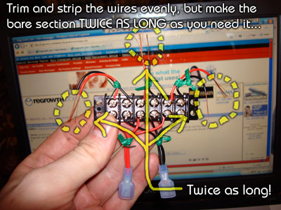
HOWEVER, since the disconnects are a little too big for one wire, we need to expose twice as much as we need, and then fold them over:
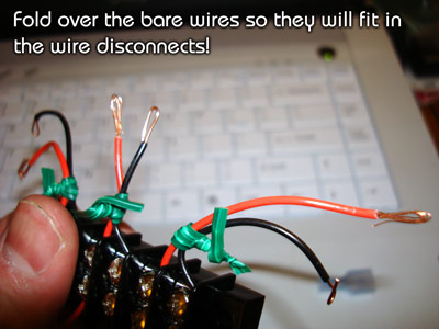
This way... they will fit in the wire disconnects, and you can crimp on the remaining wire disconnects:
And you have a finished "Flux Capacitor"! Now... all you have to do is cut velcro to fit the back (I put it at approximately the width of the center four screws because that is about the amount of surface that makes contact with the helmet because of the curvature):
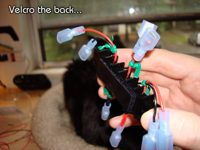
...and stick it on!
If the velcro doesn't want to stay on, add some super glue!
SECTION 7: Finish it!
In this last step, we are simply going to trim the "level 3 connection wires" and attach the opposite, corresponding wire disconnects!
So, similar to the previous step, trim the wires, strip them so you have enough bare wire, and fold the bare ends...
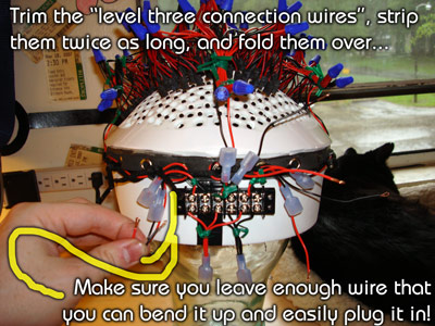
How much wire do you want to leave when you trim it? You want to leave enough that you can still bend the plug up to plug them together!
Ok, so put the female disconnects on the remaining "level three connection wires"...
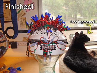
...test each section if you want to:
...and YOU ARE FINISHED! Obviously, you plug and unplug the device to treat the zones you want to treat (much easier to make than "switches" that require soldering), and you now have the choice:
All at once, or one zone at a time!
All that's left for you to do is add the corresponding "wire disconnects" to your power supply, and it's ready to go!
FINAL THOUGHTS:
This is a good laser helmet. I started building it in search of a cheap and easy way to build a helmet that meets the not only the standards that I require, but one that overcomes the typical design flaws and pitfalls of many helmets that I've discovered since December 6th, 2007. ...And when I say "cheap and easy", I mean so "cheap and easy" that MOST PEOPLE could make it with commonly found supplies, without difficult tools (no power tools, either), and without much skill.
HOWEVER, in the manufacturing process, I discovered that this wasn't just a helmet for the people that were lacking tools and skills, but it's a design that is on par with -if not surpassing- most laser helmets out there. I couldn't be happier with it, and I'm happy to say that now that I see the finished product, I would actually PREFER this one to ANY OTHER DESIGN I CAN THINK OF.
This is probably a question that most people have... "Is it heavy? Does the weight of the diodes push down on the brush bristles?" Yes, it's kind of heavy (I guess for a helmet... it's probably about two or three pounds), but the design does disperse the weight very well so the bristles aren't a problem. Also, and this is something important, if the top and the bottom of the helmet are "fused together" by lacing them together as one (that's covered in the first set of instructions, and something I STRONGLY recommended), then the TIGHTER you get the headband, the more the weight of the diodes (and the pressure of the bristles) will be alleviated! In fact, if I make the headband tight enough (and it's still very comfortable due to the 6mm foam padding), I can place it on my head so that it gets the diodes completely OFF OF MY SCALP, so the brush bristles aren't even touching! ...And, of course, it's still conforming to the scalp and holding it's form! That was a huge hurdle to overcome, and I'm glad I did it successfully!
The weight of the bristles will still more-than-likely be noticeable when they are on your scalp, but not painful or annoying, and it's something that you get used to very quickly. So, don't fret about that part!
Also, the coverage of your scalp by this design is unsurpassed. It mimics the gutter guard pretty closely, and it follows the curvature of your scalp. Obviously, the bristles ensure the most even dispersion of power that you can hope for.
One other thing, the "switchable zones" you've added are a fantastic experiment! If it proves out to be what I think it is -which is something that provides an extra "scalp exercising" benefit that most other laser helmet's can't replicate- then you will enjoy your results (and maybe even more profound results) than even laser clinics. If I'm wrong... it certainly doesn't take away from anything, and you can always run all the zones at the same time. You were out about $10 and maybe 45 minutes tops adding those switches, and you have a potential to possibly increase your results (both short term and long term) immensely, without any risk of less results!
Finally, ENJOY IT! You've done one of the BEST THINGS you can possibly do for your hair by building this. I'll remind everyone right now that when I made my first laser helmet... I didn't know what to expect. It took a solid 3 1/2 months before I noticed anything positive, and those were a LONG 3 1/2 months! I didn't know whether I was wasting my time or what! Well, you have an advantage... when YOU are going through that tough period of time before you notice results, allow yourself to have some "Peace of Mind"! You know you are doing something great for your hair! Relax, keep using it three times a week, 20 or so minutes per zone, and the results will come!
Hey... it was *fun* building this thing, wasn't it? lol... See you at OverMachoGrande.com! ...And if you want to repay me, Romeo Y Julieta Reserva Real Toros! ;)
-O.M.G.
PS- Why did I take the time to do this? Let me answer that with another question: WHY HAVEN'T YOU?

The FINAL PART --and a great wiring overview!!!
.jpg "The World's Greatest Laser Helmet for Hair Loss")
.jpg)
.jpg "EMFs and Laser Helmets")
.jpg "Lasers vs. LEDs -there is no competition!")
.jpg "Calendar of Laser Therapy Usage")
.jpg "Additional Common Coverage Patterns of the Laser Messiah II")
.jpg "PulseDrive Introduction Video")
.jpg "Common diode patterns for the Laser Messiah II")
.jpg "The Laser Messiah II works WORLDWIDE!")
.jpg "The laser helmet for hair loss that changed the world")
.jpg "Fitting Instructions for the Laser Messiah Video Screenshot")
Comments (0)
Login | Register