Wiring is Ridiculously Easy!
.jpg)
DISCLAIMER! My "Wiring of the Laser Messiah" and my "Wiring Updates" PDFs have much more current instructions/concepts for wiring much greater amounts of diodes, but this is still a great article! It shows the very basics, and it's in both the "Must Reads and the "DIY" section! Enjoy my graphics, ha ha!
.jpg)
Laser Diodes have circuitry built in, so all you have to do is wire them "parallel" to a proper power source and it works! Wiring "parallel" simply means that you connect all of the red wires of the diodes together and connect them to the positive side of the adapter, and connect all of the black wires of the diodes together and connect them to the negitive side of the adapter.
I have seen diagrams were people have wired them "series"... and this is incorrect (for the amount of volts they were using). Wiring series is basically a "daisy chain", where the red wire of the first wire is wired to the black wire of the second diode, and so on. This causes the volts from the power source to be split, and we don't want this!!!
There are ways to wire them in combinations of series/parallel, and you can also use resistors for extra protection, but I haven't done any of this at this point and I'll update the site if I do. But for now, we are going to stick to the simplest way to do this!
Once again, for a better description of the tools you need, check out the "Do-It-Yourself Introduction (Revisited!) and Checklist". This is just so you can solve the mystery of what is going on with all that wiring, and see it in an easy layout with my beautiful, Rembrant-style graphics...
Wiring the Adapter/Power Supply...
Let's start with wiring the adapter/power supply. I have more details in several other sections about the requirements of your power supply, but in a nutshell... you need one that has the volt requirements of the diodes, and has enough amps for ALL the diodes. For example, the diodes I use are 3.2 volt, 30mA. No, you won't readily find a 3.2 volt adapter, but a three volt one will work just fine. They draw 30 milliamps (mA) apiece, so that means if you have 10 diodes, you need an adapter that has at least 300 mA. If you have 100 diodes, you need one that has at least 3000 mA (or 3 amps), and so on.
If your amp requirements are pretty low, you can get your adapter from Radio Shack and skip this step... there omni adapter has a tip that will work with the "Hobby Lead Adaptaplug". However, if you get an adapter from somewhere else, you are going to need a "matching set" of plugs so you can plug your lasers into that adapter. This is where Radio Shack comes in! They have a set here, and each cost about four bucks...
1) "Replacement Adaptaplug Socket": [This part seems to be no longer made --no worry, though! My other instructions show much better connectors!] This is the part that you attach to your snipped adapter wire. You just strip all of the wires back, and attach them together by twisting and electrical tape!

...and think positive thoughts for Radio Shack!
They've played a huge role in the
lives of Do-It-Yourselfers!
2) "Hobby Power Leads Adaptaplug": [This part ALSO seems to be no longer made --no worry, though! My other instructions show much better connectors!] This is the part you attach to all of the wires of your laser device! You may need to strip back a lot of the wire on this since you might have a ginormous twisted mass of wire that you have to wrap it around.

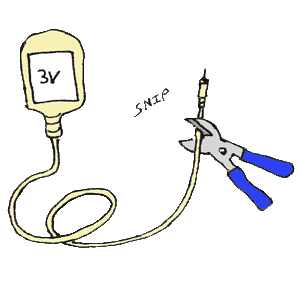
Ok, so here is what you do with your adapter... you snip the end off! Yep, cut it right on off:
An adapter cord is made up of two wires, a positive wire and a negative wire (just like our diodes). So what we need to next is just split the cord down the middle a little...
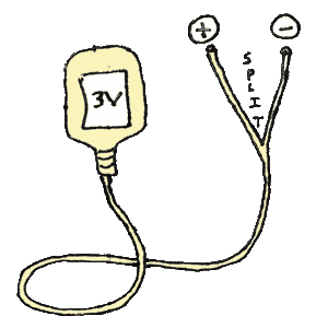
It's just a positive and a negative!
Ok, now we need to expose the bare wire on both the positive and negative side, so we use the wire strippers here:
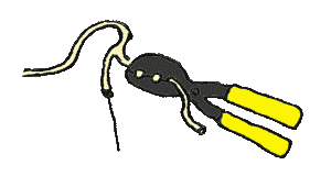
This is where our first Radio Shack part comes in: the ""Replacement Adaptaplug Socket". You'll need to use the wire stipper a little bit here, too, because they only have a very small amount of bare wire, and the easy way we wire them requires a little more...
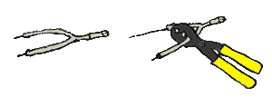
Ok, you twist the two parts together... the positive side of the adaptaplug socket to the positive adapter wire, and the negative side of the adaptaplug socket to the negative adapter wire. [Note - The positive wire of the adapter may NOT be marked... so you might have to guess here. 50/50 shot! If you guess wrong, it won't hurt the diodes... it just won't work. Worst case scenario you have to come back and switch it.]
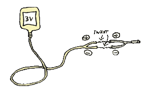
You might have to guess which side is + and -. 50/50 odds!
Electrical tape them together! This is to shield them and to secure them in place. In my experience, this part of the cord can take a lot of abuse, so you may want to take the time to make them extra secure!
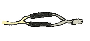
...but this is just basic wiring concepts here!
Finally, electrical tape them both together, and you are finished!
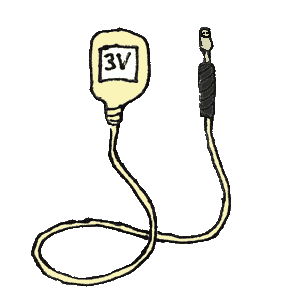
Wiring the Diodes...
There isn't much to this either! You already have the adapter wired, so now all you have to do is essentially bridge a connection between positive wire of the adapter to the red wires of the diodes, and the negative to the black. You do this with the second Radio Shack part, the "Hobby Power Leads Adaptaplug".
This diagram shows a layout of all of the part in play, including the use of red and black wires as an "extension chord" from the diodes to the second Radio Shack part. This is really ALL that's involved for making diode "light up" at full power...
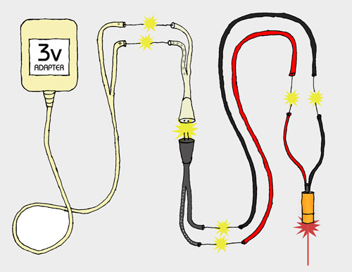
What about two diodes? Well, it's the same thing... you simply connect the reds of the diodes together, and blacks of the diodes together:
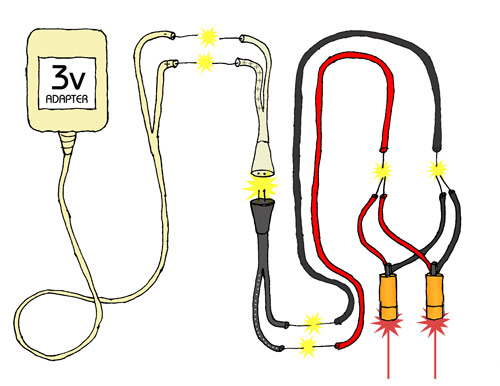
You can go way up from here! Just make sure you have enough AMPs!
What about ten?? ...You're starting to get it! I have ten in my "Original Laser Brush", and it's done the same way. You can see in the picture that I have them grouped together:
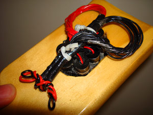
Inferior, of course -but I made this at the beginning of the journey!
EMAIL ME for the end result of the journey, the Laser Messiah II!
SIXTY-EIGHT?! Yep... you guessed! As long as you have an adapter/powersupply with enough amps, the sky is the limit here, You can see in this picture that on my Laser Helmet, I have corralled the wires into two seperate directions:
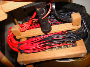
(20 minutes a section) CAN give you results!
Ok, that's it! You can arrange, attach and/or hide these wires to your device to your liking!
I might one day (when I have extra diodes... I'm currently fresh out of them) put together a quick video, maybe just to see how quick I can get a couple up and running. Think I can do it in less than a minute?? Maybe we'll see one day! ...It's that easy!
It's even easier with the TRC Electronics 3.3 volt/ 7 amp Switching Power Supply!
Look at this... you can even skip the two Radio Shack parts with this! Obviously, you still connect all the reds of the diodes together and blacks of the diodes together and run them into the corresponding ports, but it's very easy...
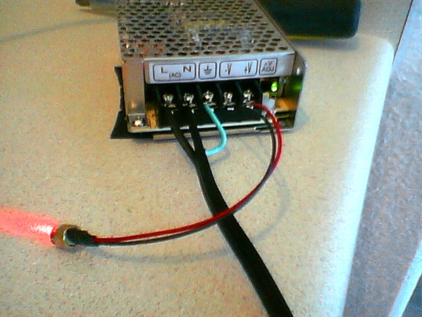
I use MUCH MORE ROBUST ONES with my Laser Helmets that can run up to 450!
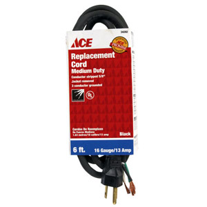
You need to get a power cord from Home Depot or Lowes, and then you run the live, neutral, and ground into the left side, and the negative and positive wires of the diode into the right size. I haven't used this, but ChipDouglas found it, and Lemming is using it (and provided all of these kick-ass pictures!), and I will more than likely use it for my next project (with 210 diodes). For more info on this power supply, go to the "Power Supplies/Adapters" page.
Here is an example of the type of power cord you need. If you look really close, you can see that the end of the cord has three sections, colored green, black, and white:
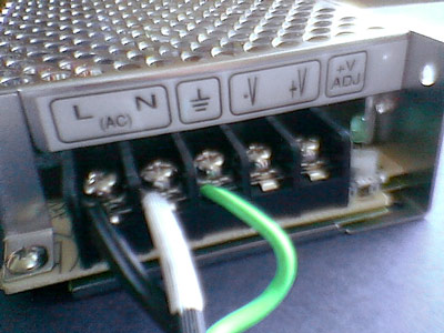
...And here is a close-up of the TRC:
Your country may differ. Brown/Blue/Green-Yellow is common throughout the UK and Europe!
The black is your "live" wire and goes in Pin 1, the white is your "neutral" wire and goes in Pin 2. and the green is the "ground" wire and goes in Pin 3. Thanks, Lemming!
-John (O.M.G.)
I'm ALWAYS here to answer email!

.jpg)
.jpg)
.jpg)
.jpg)
.jpg)
.jpg)
.jpg)
.jpg)
.jpg)
.jpg)
.jpg)
Comments (0)
Login | Register